Mechanical design engineers using SolidWorks CAD
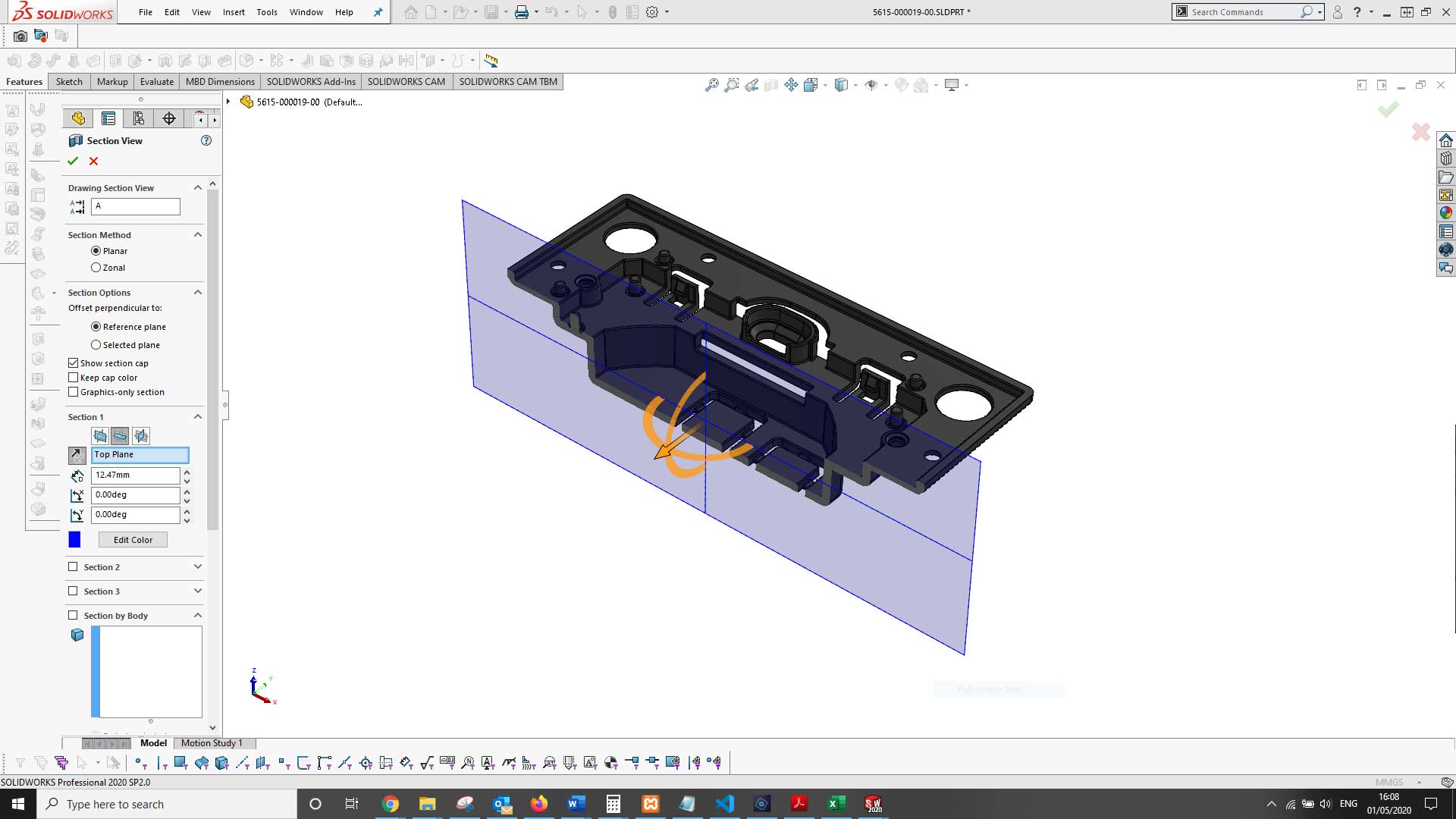
SolidWorks is a sophisticated CAD platform that enables us to engineer products accurately. For anyone who isn't familiar with Solidworks, it is a parametric modelling system which means components are modelled on a computer using a series of rules or parameters. Parametric modelling is extremely accurate as it uses exact geometry referencing for the parameters, which means features can be modelled with precision. It also allows changes to be made to certain parameters later.
Components are detailed on SolidWorks in various ways depending on their complexity and the areas that may require change later. Typically, a part will start its CAD life as a 3D model – this may be a block that has features added to it or removed from it until the final part is complete. While this may sound straight forward and simple to some, there is a considerable thought process involved at every step. Each feature, each line, each point has been strategically created to fulfil the requirements of the part.
Depending on how the part is manufactured, different formats of data can be created from it. In the majority of cases, a complimentary 2D drawing of the parts is also created. A 2D drawing provides details of essential geometry, materials and finishing. Some manufacturers use 2D drawing to fabricate parts, and others use both 3D and 2D data. We are highly experienced in creating both 3D components and 2D drawings.
Some parts are relatively simple to draw on CAD, and others are very complicated, but it's not always obvious.
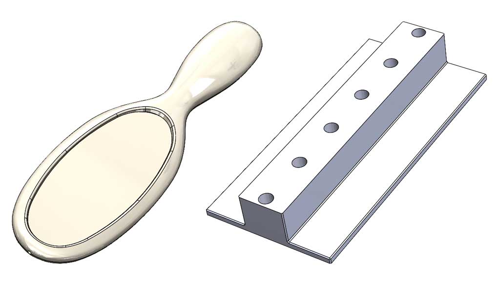
The two parts illustrated above are similar in size yet one, the hairbrush handle, took considerably longer to draw. The reason? Geometry. If you look closely at the hairbrush handle, you'll see it's based on surfaces that are curved in multiple directions. Reproducing parts like this can take time. Each curved surface is directly related to another and is comprised of many compound curves, each defined accurately with a set of dimensional parameters.
Creating product assemblies
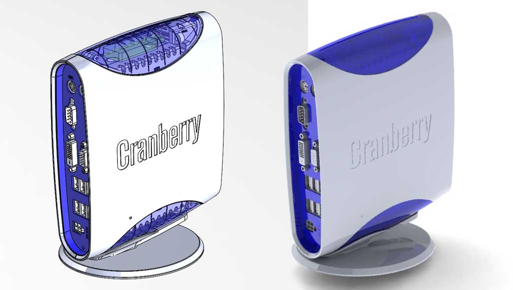
Parts can be positioned in assemblies on SolidWorks to test for fit and tolerances. A complete virtual model, in 3D, of a finished product can be created. This can often include every last detail down to the individual screws used in the assembly, graphics or decals, and even textures. It is possible to create an assembly of a product and render it to produce a photorealistic image for marketing and promotional applications. In the automotive industry, many images of new vehicles are actually 3D renders that have so much detail, it's almost impossible to tell the difference.
Simulation
One useful function of CAD software is its ability to run various simulations. These can include simulations to understand the flow of heat, air and liquids as well as forces. We have some limited simulation capability that enables us to perform simple finite element analysis (FEA) on components, to check for loading capability and stress. We can identify if a part is likely to fail during its normal operation and optimise the part to ensure it remains functional throughout the products life.
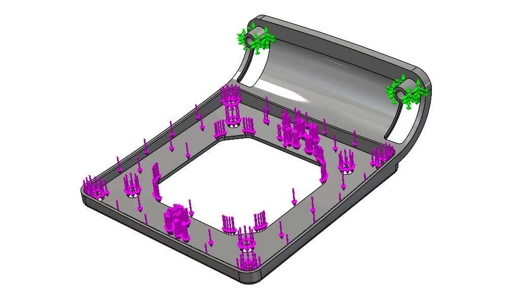
Stress analysis
Stress analysis is one of the most common simulations. It tests the physical characteristics of a part without having a real part to test. It works by creating a mesh of the part, composed of several points, that can be evaluated for a given load and restriction. We can identify if a part is likely to fail structurally before it has even been produced. For parts where loading is critical, this is a very important element of the design process.