How reverse engineering helped protect a prestigious UK business
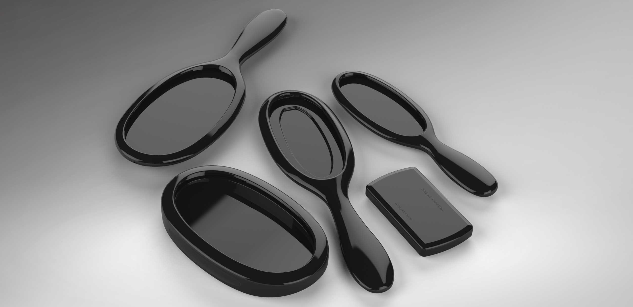
Mason Pearson is a prestigious hairbrush manufacturer based in the UK, with its roots in the peak of the Industrial Revolution. Their range of hairbrush designs, sold to the more exclusive markets, have remained the same since the business was started over a century ago.
Their products, manufactured in Essex, UK, are produced using a combination of modern production technology and skilled craftsmanship. The products are made to meet an expected standard, outperforming cheaper alternatives due to tightly guarded production methods.
We were asked to produce a up-to-date CAD data of their product range for two reasons. Firstly, some of the injection moulding tools still in use were very old and would eventually require replacement. Secondly, in the event of a complete factory disaster or irreversible damage to their production tools, they would have some data to be used for quick recovery.
As years take their toll on tooling, injection mouldings effectively change shape and post-injection processes are modified to suit. We were given a set of raw hairbrush handles to reverse engineer into 3D data from which we could produce accurate tooling data and 2D information. Some people might consider this a fairly easy process, but there was a great deal of accuracy involved to ensure the final shape of each design was replicated well enough and adjusted to correct any deformation caused by tool wear.
The first attempt at replicating a product in 3D
When we first attempted to replicate one of their handle designs, we created various sections of the hairbrush profile and measured key points as accurately as possible. We then put these measurements into our CAD system to create a CAD model of the hairbrush handle. The handle was prototyped using a stereolithographic process to produce a physical model that we compared with the original. It looked good initially, but when comparing it to several moulded samples, some deformations were obvious. The curves that we created in each profile were interpreted based on closest measurements, and while it was difficult to spot the differences by eye, they could be felt by finger.
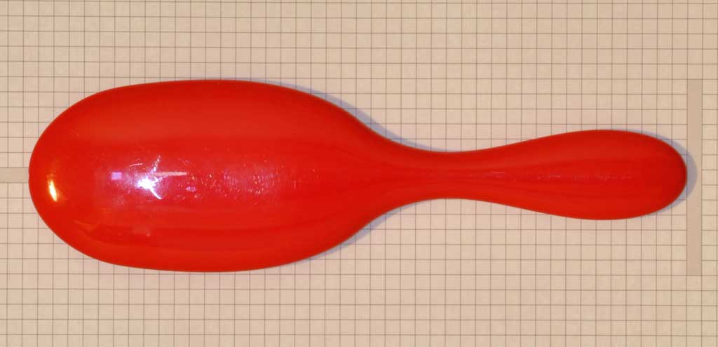
The first prototype made from measured data
Reverse engineering using a 3D scanner
Taking a different approach, we invested in a compact 3D scanning system that can scan physical items with an accuracy better than +/-0.05mm. We took several moulded samples to produce scanned data that we used as a basis for our final CAD designs. With scanned 3D data, it is possible to superimpose a parametric model over the data, essentially copying it using 'clean' geometry. Combined with section measurements taken along geometrical points that were key or critical, the data we created was far more accurate than just utilising section profile measurements.
We had several prototypes printed using a very fine stereolithographic process that was evaluated, and the results were good. The CAD models were used to produce the relevant production data - including 2D reference drawings - ensuring that the products could be replicated in the future, using the CAD data we defined.
3D scanners have remarkable abilities
3D scanning is quite a remarkable process that uses a series of reference points and lights to define the contour of a profile. The only disadvantage of the process is it can only scan items that are visible or in line of sight of the scanner. That's because light can't reflect from hidden pockets or cavities. The scanning process is very accurate, but as a result, the data that's generated can be complex. The reason for this is because of how the data is related to the scan. 3D scanners do not create parametric relationships between measured points, but instead, produce a disjointed cloud of points that are then stitched together by the relevant software.
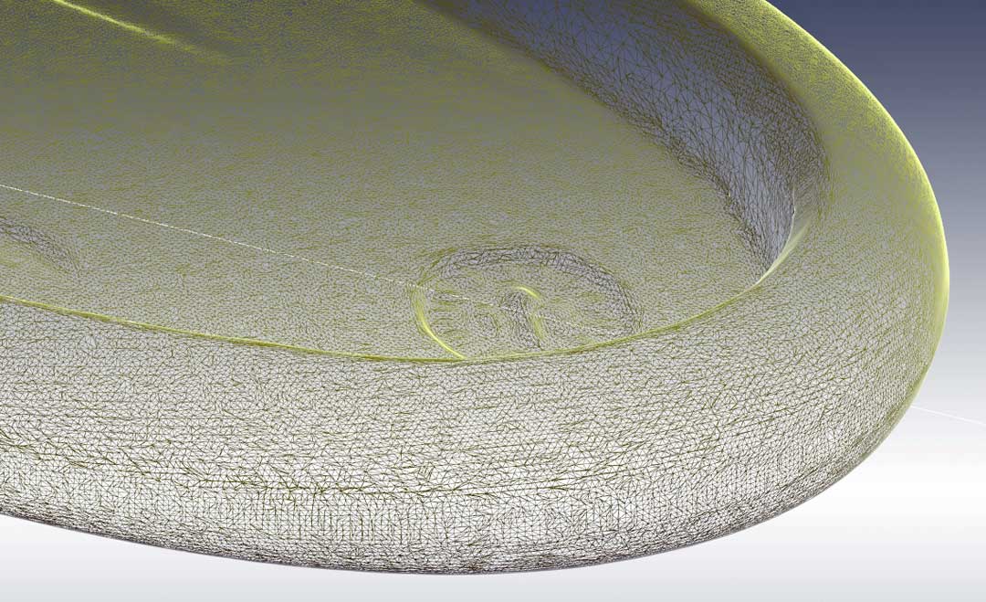
A wire-mesh of a moderately detailed 3D scan of a hairbrush handle.
The image above is a wire-mesh close-up of one of the scanned handles. You can see how many points there are just in this localised area, and this isn't even a high resolution scan. Notice the faded tooling index marker which in reality is just a fine surface impression. The 3D scan is very accurate, but there are millions of points. There was also an undercut feature that couldn't be scanned because it was hidden out of view. The undercut feature was replicated on the final CAD model using measurements that were taken from several cut profile sections.
An item the size of a smartphone can easily produce tens or hundreds of millions of points of data, depending on how accurate the scan needs to be. Even a surface that looks flat will be scanned with thousands of points across the surface. It is possible to clean the data to reduce the number of points and to define relationships between them, but this increase the risk of physical inaccuracies. So instead, the data is used as a guide allowing parametric data to be modelled directly over it. Parametric data ensures efficient CAD designs and production data that can be used for the accurate manufacture of parts.
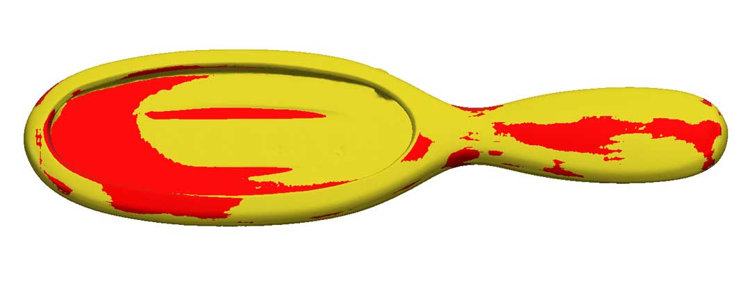
Superimposing scanned data over modelled data
The image above shows how 3D scanned data can be used to create accurate parametric geometry. The yellow surfaces are those that were scanned and the red surfaces are those that were modelled using geometric relationships. You can see where the scanned data produced inconsistencies in the symmetry. This is due to small deformations in the injection moulded part, deviating from the expected symmetry.
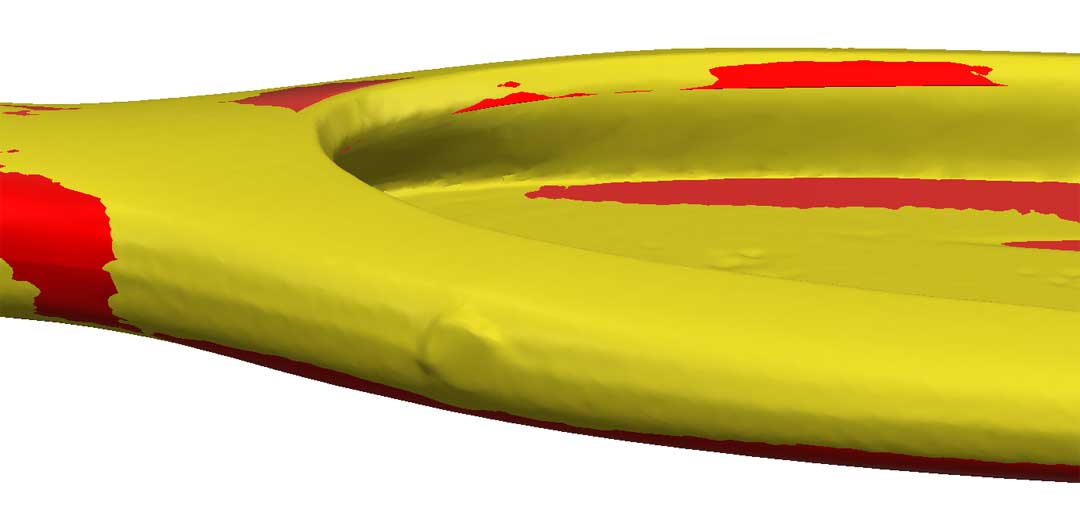
A close up of the superimposed data
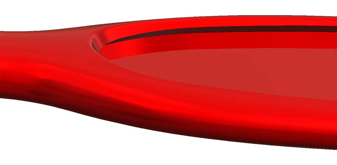
You'll notice in the image above lots of small lumps on the surface (in yellow) and a larger, more pronounced bump which is a mark left by the sprue. If we used the yellow data directly, our final data would have too many imperfections. Using 3D scanned data correctly relies on some manipulation of the information created. The image below shows just the ‘clean’ parametric data with no lumps or marks.
If you have a project that might require reverse engineering, we can help you produce accurate CAD data and make any necessary changes. Get in touch with us today to find out more.